Mechanical estimating is one of the most technically demanding disciplines in commercial construction cost engineering. A single commercial project encompasses hundreds of ductwork transitions, variable air volume (VAV) terminals, chiller and boiler equipment schedules, and complex hydronic piping loops. MasterFormat Division 23 estimating requires a rigorous, systematic methodology to convert mechanical drawings into a profitable, bid-ready proposal.
1. Foundations of Division 23 Quantification
A dependable mechanical estimate begins with an exhaustive scope separation. Mechanical estimators review mechanical drawings (M-sheets), architectural reflected ceiling plans (RCP), and structural framing plans to identify ceiling plenum heights, structural beam clashes, and roof curb penetrations.
Division 23 scope breaks down into four interconnected categories: air distribution and sheet metal ductwork, hydronic piping and pumps, central plant equipment, and automated temperature controls (ATC / BMS). Isolating these categories ensures that material costs and specialized labor units are applied accurately.
Scope & Standards Clarification
This guide outlines professional estimating and quantity takeoff methodologies. It is intended for contractor bidding and preconstruction budgeting, not as a substitute for professional engineering design or municipal code compliance. References to industry associations (such as SMACNA or MCAA) are for general educational context; Smart Scale Estimators does not reproduce or claim ownership of proprietary association standards.
Explore Commercial Mechanical Estimating Services2. Reconciling Equipment Schedules
The first quantitative step in any mechanical estimate is auditing equipment schedules against floor plans. Blueprints frequently contain discrepancies between schedule tags and drawing layouts.
Key Equipment Verification Milestones
Mechanical cost engineers cross-reference every major equipment tag on the plan sets:
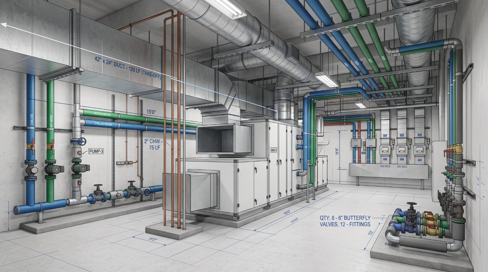
- Air Handling Units (AHUs) & Rooftop Units (RTUs): Verify CFM capacities, tonnage, heating/cooling coil types, electrical voltage requirements, and roof curb details.
- Variable Air Volume (VAV) Boxes: Reconcile schedule counts against ductwork layouts, noting electric reheat vs. hydronic reheat coils.
- Chillers, Boilers & Cooling Towers: Confirm cooling capacities, manufacturer basis-of-design specifications, vibration isolators, and rigging requirements.
- Exhaust & Supply Fans: Count inline, wall-mounted, and roof exhaust fans, verifying sound attenuators and backdraft dampers.
3. Calculating Sheet Metal Ductwork & Air Distribution
Ductwork is rarely estimated solely by linear footage; commercial sheet metal is priced, fabricated, and installed based on surface area and calculated weight. In commercial mechanical estimating, sheet metal gauge thickness and construction requirements depend on duct dimensions, static pressure class, joint reinforcement spacing, and project specifications.
Rather than relying on unverified generic assumptions, professional estimators consult the engineer-of-record specifications and recognized industry references (such as SMACNA guidelines) to confirm required sheet metal gauges for each static pressure class. Once the gauge and metal type (galvanized steel, stainless steel, or aluminum) are confirmed, total surface area is converted into gross poundage to model fabrication and handling time.
| System Component | Primary Takeoff Metric | Key Sizing & Scope Drivers | Typical Material & Joint Standards |
|---|---|---|---|
| Rectangular Supply & Return Duct | Surface Area (Sq. Ft.) & Steel Weight (Lbs) | Duct width x height, static pressure rating, internal acoustic lining | Galvanized steel; transverse duct connections (TDC/TDF) or slip & drive |
| Round Spiral & Oval Ductwork | Linear Footage & Diameter / Minor Axis | Airflow CFM, velocity limits, exposed architectural vs. concealed | Spiral lock-seam galvanized pipe with self-sealing gasketed fittings |
| Hydronic & Refrigerant Piping | Linear Footage by Pipe Size & Schedule | Operating fluid (chilled water, hot water, refrigerant), system pressure | Black steel (Schedule 40 welded/grooved), Type L copper, press-fit systems |
| Central Plant Equipment | Unit Count & Schedule Capacity | Cooling tons, MBH heating, electrical characteristics, operating weight | Manufacturer basis-of-design schedules (RTUs, chillers, boilers, pumps) |
| Air Distribution Terminals & Dampers | Piece Count & Connection Size | CFM rating, neck size, throw pattern, fire/smoke damper hourly rating | UL-listed fire/smoke dampers, motorized control dampers, diffusers & grilles |
The 4-Step Ductwork Calculation Workflow
Mechanical estimators calculate total ductwork fabrication quantities through a consistent 4-step workflow:
1. Calculate perimeter: For rectangular ductwork, Perimeter = 2 × (Width + Height) in feet.
2. Determine surface area: Surface Area (sq. ft.) = Perimeter × Linear Length of straight run.
3. Apply gauge weight factor: Multiply surface area by the specified metal unit weight (lbs/sq. ft.) corresponding to the engineer-specified gauge for that pressure class.
4. Factor fitting and seam allowances: Add a standardized fitting allowance (typically 15% to 25%) to account for elbows, transitions, offsets, turning vanes, seams, and hangers.
4. Hydronic & Refrigerant Piping Takeoffs
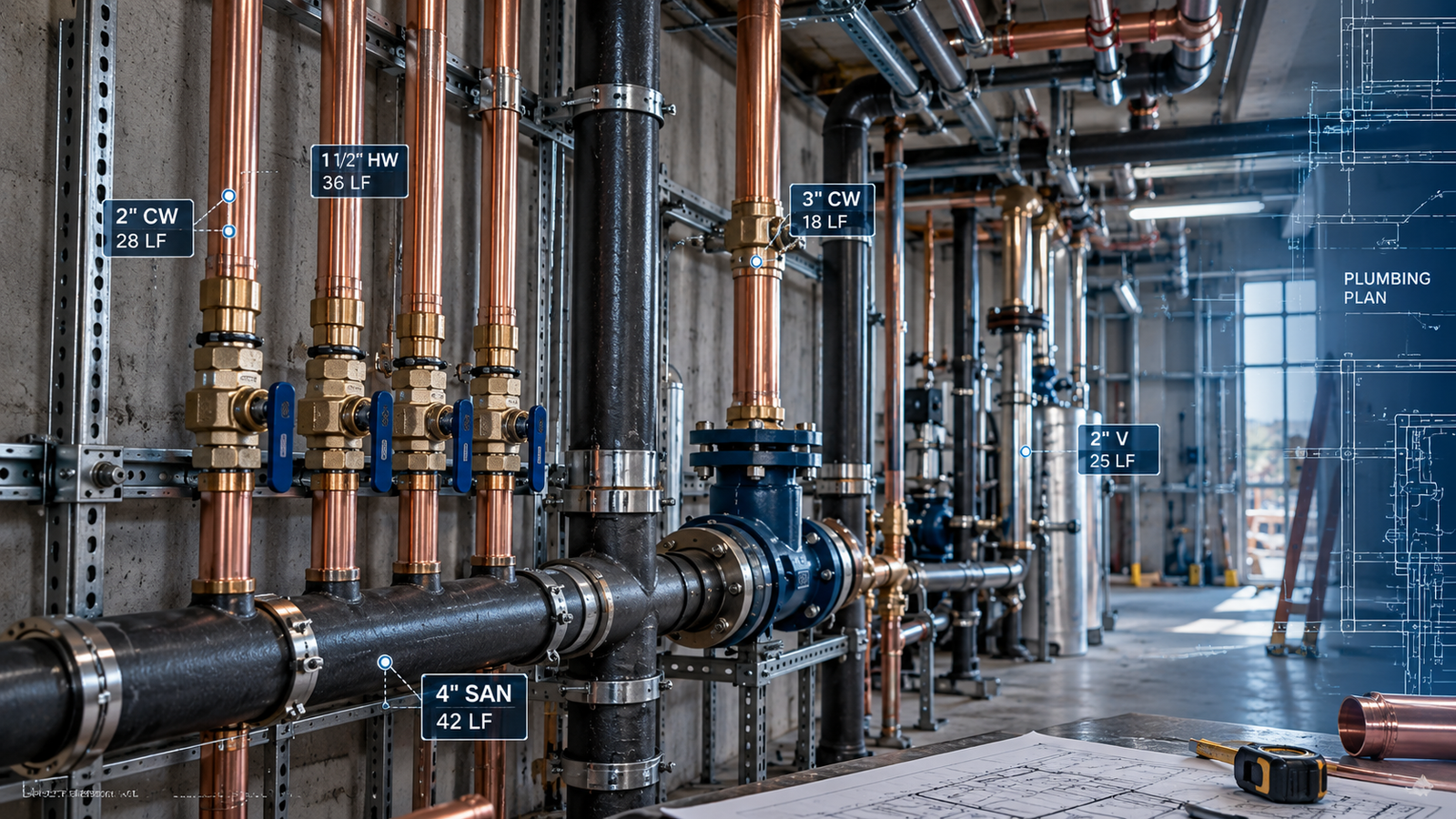
Hydronic piping systems circulate chilled water, heating hot water, and condenser water between central plants and terminal units. Piping takeoffs must separate linear footage by pipe material (Schedule 40 black steel, copper Type L, stainless steel), diameter, and joint method (welded, grooved/Victaulic, threaded, soldered).
In addition to straight pipe runs, estimators must quantify specialty accessories: balancing valves, triple-duty valves, strainers, flexible connectors, expansion tanks, and pipe insulation thickness specified under Division 23 thermal insulation.
5. Labor Productivity Modeling & Quality Control Review
Material quotes for ductwork and chillers are relatively stable; labor installation hours represent the highest financial variance in any mechanical bid. Professional estimators determine labor installation hours using established industry productivity guidelines combined with contractor-specific historical production data.
Labor units must always be adjusted to actual project conditions rather than treated as static figures. Working in occupied healthcare environments, high-bay warehouses requiring scissor lifts or scaffolding above 14 feet, congested multi-trade ceiling plenums, or urban downtown cores requires productivity adjustment factors ranging from 1.15 to 1.40.
Before bid submission, the complete takeoff package undergoes an internal quality review: comparing total duct poundage per square foot against historical building benchmarks (typically 1.2 to 2.2 lbs/sq. ft. for commercial office space) to confirm order-of-magnitude accuracy.
Review Audit-Ready Mechanical Deliverables
See how Smart Scale Estimators formats Division 23 ductwork poundage, piping runs, and equipment schedules in our publicly downloadable sample library.
Inspect Mechanical Estimate SamplesFrequently Asked Questions
Commercial ductwork varies continuously in width, height, and gauge thickness along a distribution run. Pricing by poundage accounts for the true amount of galvanized steel, fabrication time, and handling weight required to build and hang the system.
Estimators typically apply a 15% to 25% fitting allowance to straight rectangular duct poundage to account for elbows, transitions, radius offsets, seams, and drive cleats.
Commercial mechanical estimators reference project specifications alongside recognized industry guidelines (such as SMACNA duct construction principles) and contractor-specific historical labor data. Labor hours are adjusted based on job site conditions, elevation, and installation complexity rather than relying on unadjusted static national tables.
Estimators maintain an addenda log, overlay revised drawing revisions in vector software (such as Bluebeam Revu), identify delta clouds, and update affected duct lengths, piping runs, and equipment capacity schedules before bid day.